Exhaust Articles - Front-Wheel Drive Articles

Troubleshoot Exhaust Noise & Leaks
Copyright AA1Car Adapted from an article written by Larry Carley for Brake & Front End magazineShort trips, especially during cold weather, leave a lot of condensation in the exhaust system. The muffler and pipes never get hot enough to evaporate any collected water.
If the muffler is mounted far from the converter in the rear of the vehicle, the moisture will puddle inside the muffler and rust it from the inside out. Water combines with sulfur in the exhaust to form highly corrosive acids that eat away at the metal.
Inspect Exhaust System
Start your inspection at the engine and go all the way back to the tailpipe. One place where exhaust leaks often develop and go undetected is where the exhaust manifold mates to the cylinder head. The thermal expansion and contraction that occurs every time an engine is started, driven and shut off creates a lot of shear stress on the exhaust manifold gasket. After several years, it's not unusual for small leaks to develop. And over time, the small leaks usually get bigger.Exhaust Leak Dangers
Exhaust leaks should never be ignored because they can have serious consequences any time of year. Because it is colorless and odorless, carbon monoxide gas can be lethal, especially if the windows are rolled up and the deadly gas finds its way inside the passenger compartment.Test The Exhaust Pipes
Use a large pair of expandable pliers to test suspicious pipes. The pliers will tell you if the pipes are rotten or solid. If the pipe gives when pressure is applied, it needs to be replaced. Poking at rusted areas on the muffler, resonator or converter shell will also tell you if the corrosion is on the surface or goes all the way through the metal.
Exhaust Noise
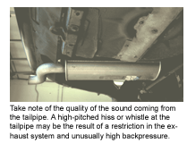
Another source of buzzing noises in the exhaust, especially on high revving four-cylinder engines, is harmonic resonance. This is typically loudest at certain engine rpms and/or when accelerating hard under load. Original equipment exhaust systems are typically tuned to dampen the more annoying high pitched tones, which is why many OE exhaust systems have a second muffler or resonator. The length, shape and chamber design of the resonator is designed to silence certain sound frequencies in the exhaust.Exhaust Restriction
If a vehicle has been getting poor fuel economy or has a loss of power, the exhaust system might have an internal restriction or blockage. Exhaust system restrictions can be caused by damaged or crushed pipes, or collapsed baffles inside a muffler or resonator. But the most common cause these days often turns out to be a plugged catalytic converter.Exhaust Backpressure
Backpressure can be measured directly several ways. One is to measure it at the air pump check valve. Remove the check valve and install a pressure gauge. However, the check valve must connect to the exhaust system ahead of the converter. (Note: if the plumbing hooks up at the converter, this technique won't give you reliable results.)Plugged Catalytic Converter
You can also check for a plugged converter by removing it, holding a shop light at one end and peering in the other end. With honeycomb-style converters, you should be able to see the light. No light means a plugged converter.
When that unburned fuel hits the converter, it ignites, sending the converter's operating temperature soaring. This breaks down and melts the honeycomb substrate that supports the catalyst, creating a partial or complete blockage.
If a muffler or resonator has failed, don't replace it without checking the integrity of the pipes on both sides.
More Exhaust System Articles:
How to Replace a MufflerCatalytic Converters
Performance Mufflers

CV Joints
Copyright AA1Car
Constant Velocity joints (CV joints) are used on both ends of front-wheel drive (FWD) axle shafts (also called halfshafts). The CV joint is the flexible coupling that allows the outer wheel to steer, and the shaft to follow the up and down motions of the suspension as the vehicle travels down the road.
The outboard CV joint (the one that connects to the drive wheel) typically has a much wider operating angle than the inboard CV joint that connects to the transaxle. This is because the outer joint may have to turn up to 50 degrees off center when the front wheels are steered. The inboard joint, by comparison, rarely sees an operating angle of more than about 20 degrees. Consequently, different types of joint designs may be used for the inner and outer joints.
Outboard joints that do not plunge in and out are called "fixed" joints.
RZEPPA CV JOINTS
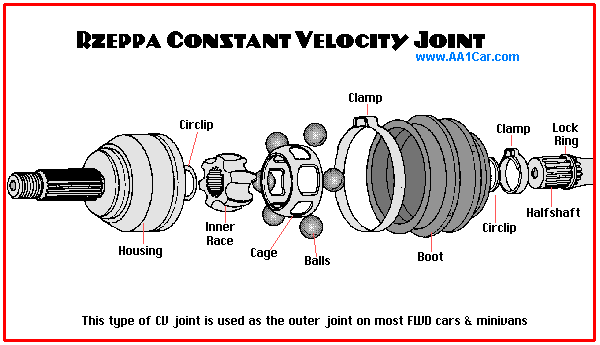
The most common type of outboard CV joint is the "Rzeppa" style. This type of joint was invented way back in 1920 by a Dana engineer named Alfred H. Rzeppa. His design allowed power to be transmitted through six spherical balls located between an inner and outer race. In this design, the balls are held in position by small windows in a cage assembly that fits between the inner and outer races. The design of the joint is such that the position of the balls always bisects (cuts in half) the operating angle of the joint. It is a slick design that works something like a bevel gear. But instead of gear teeth transmitting the torque across the joint, the balls push against their respective tracks in the inner and outer housings.

DOUBLE OFFSET & CROSS GROOVE CV JOINTS
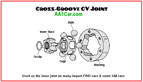
A couple of variations on this design are the "double offset" (DOJ) and "Plunging Disk Type Cross Groove" CV joints. Both designs also have the six ball arrangement, but the joints are used only on the inboard end of the shaft. Both designs allow the inner race (which is mounted on the end of the shaft) to "plunge" in and out so the shaft can change length. Why is this necessary? Because the shaft is usually longer than the control arms on the suspension. The difference in length would create interference problems every time the suspension moved up or down.
So the plunging action of these joints allows the shaft to slide in and out slightly to compensate for the difference.

TRIPOD CV JOINTS
The other type of CV joint you will see is the "tripod" style joint. Tripod joints do not have balls but instead use needle bearing rollers mounted on a three-legged spider. The rollers are mounted at 120 degrees to one another and slide back and forth in tracks in an outer "tulip" housing.
Tripod style joints are used for the inner joints on most domestic and Asian FWD models from 1983 to present. This type of joint is less expensive to manufacture than a ball type joint, and is well-suited to the limited operating angles of the inner joint location. The joint is designed to plunge in and out the same as other inboard joints to allow changes in shaft length as the suspension moves.
A fixed version of the tripod joint is used on a few applications including the former AMC Alliance and some Asian applications (Toyota Tercel and Nissan Sentra).
WHY A CV JOINT AND NOT A U-JOINT?
Have you ever wondered why front-wheel drive cars do not have ordinary universal joints? U-joints work fine on the driveshaft in most rear-wheel drive applications, so why not FWD too? The answer is because U-joints produce cyclic vibrations when operated at the kind of steering angles found in a FWD application.
Ordinary Cardan type universal joints cause a change in speed between the driving and driven shafts whenever the joint operates at an angle. As the operating angle of the joint increases, the speed (velocity) of the driven shaft varies more and more during each revolution of the shafts. The greater the operating angle, the greater the variation in speed of the driven shaft and the greater the vibration it produces.
The driven shaft still turns at the same number of revolutions per minute as the shaft that is driving it, but because of the geometry of a universal joint the speed of the driven shaft alternately increases (accelerates) and decreases (decelerates) four times every revolution, and this is what causes the vibrations we are talking about.
To visualize how this occurs, look down the length of a RWD driveshaft at the U-joint in the transmission yoke. If the tail end of the driveshaft were unbolted from the differential and lowered to the floor, it would create a severe angle in the forward U-joint. If the shaft were then turned by hand, you would then be able to see that the two bearing caps on the U-joint center cross attached to the driveshaft rotate in one plane while the two attached to the transmission yoke rotate in a different plane. All the while the center cross is swiveling back and forth with each revolution.
If you drew what is happening on paper, the two bearing caps in the transmission yoke would appear to be traveling in an elliptical (oval) shaped path as viewed down the length of the driveshaft. Or, from the other point of view, the two bearing caps on the driveshaft would appear to be traveling the elliptical path if viewed from the transmission.
So what does this have to do with speed changes and vibrations? Plenty, because it is this difference in geometry that causes the driven shaft to change speed with respect to the driving shaft.
If the transmission output shaft were turning at a consistent 1000 rpm, the driveshaft would likewise turn at 1000 rpm regardless of the joint angle. But the driveshaft would also change speed alternately twice during each half revolution because of the difference in geometry between the two opposing bearing caps in the U-joint.
The speed changes are not great when the angle is less than a few degrees, but as the operating angle of the joint increases so do the cyclic vibrations of the driven shaft as well as the back and forth motion in the joint itself.
The changing rotational velocity of the driven shaft can be offset by installing a second U-joint on the opposite end of the driven shaft "phased" 90 degrees with respect to the first joint.
In theory the second joint cancels out the changes in output velocity caused by the other joint, but only so long as both joints operate at identical angles.
This setup works fine for RWD driveshafts where front and rear joint angles are usually identical and the changes in operating angles are relatively small, but with front-wheel drive the situation is entirely different. The inner and outer joints often operate at different angles. Whenever the wheels are turned the outer joint runs at a much higher angle than the inner joint. This upsets the offsetting relationship between inner and outer joint angles that is a necessary requirement for ordinary U-joints. The front wheels are also required to steer at angles of up to 45 degrees, which puts too much strain on a U-joint.
A CV joint, by comparison, always splits the operating angle in half so the driven shaft turns at the exact same speed as the input shaft. So no matter what the joint angle, there are no changes in speed -- thus the name "constant velocity."

CV JOINT WEAR
One thing almost all FWD shafts have in common is that the outer CV joints almost always wear out long before the inner ones so. The outer joints wear at a faster rate because of the increased operating angles as the wheels steer. Consequently, the inner CV joints on many exchange shafts are in good condition and can be safely reused.
To check for wear, you have to remove the axle and disassemble the CV joint as shown above. Cracks in the ball housing, dimples or pits in the balls or races, or wear in the ball tracks would tell you the CV joint is worno ut and needs to be replaced.
Note: The balls, cages and tracks in a CV joint are precision fit with close tolerances. If you take the joint apart for cleaning and inspection, the balls must be returned to their same original positions as before.
Play between the balls and cage windows can produce a popping or clicking sound when the joint is operated at an angle (as when turning a corner). Insufficient clearance in the joint can cause binding and galling that can damage the balls and tracks as well as crack and/or chip the cage windows.
When this type of CV joint is rebuilt, slightly oversized balls and cages with oversized windows may be installed to compensate for wear. But this approach may only provide a short term fix because it does not restore the wear that may have occurred on the tracks in the inner and outer races. Because of this, many joint rebuilders now regrind the tracks on the inner race and outer housing using precision computer controlled numeric (CNC) equipment that allows the original contours of the tracks to be restored for oversized balls.
Some aftermarket FWD axle rebuilders regrind every joint as a matter of course while others only grind on an "as needed" basis. The proponents of grinding say that machining the joint restores the proper tolerances that were originally designed into it, and allows many joints that would otherwise have to be discarded because of excessive wear to be salvaged.
The tracks in the races are case hardened when a joint is originally manufactured to make the joint wear longer. Grinding obviously removes some of this hardened layer, which may create durability concerns if too much metal is removed. The depth of the case hardening on CV joints varies depending on the application and process used (induction hardening or carburizing), but typically ranges from .048 inch to .100 inch or more. So limiting the amount of material removed to .010 inch to accommodate a .020 inch oversized ball is said to have virtually no significant effect on joint life.
The key to reconditioning a CV joint by grinding, say those who do it, is to exactly duplicate the original arc in the housing and race, a process which requires precision machining equipment and cannot be duplicated by hand grinding with a simple die grinder.
CV JOINT LUBRICATION
CV joints require a special type of high temperature, high pressure grease. Ordinary chassis grease or multipurpose grease should never be used in a CV joint.
The condition of the grease as well as the amount of grease in the joint will determine how long the joint lasts. One of the purposes of the boot that surrounds the CV joint is to keep dirt and moisture out. The other is to keep the grease in. If a boot is torn, cracked, punctured or comes loose, dirt and water can contaminate the grease in the joint causing accelerated wear which will eventually lead to joint failure. Loss of grease can also occur which will further shorten the life of the joint. So the boots must be in good condition to protect the joint.

Boots often become brittle with age and exposure to heat. Boots can also be damaged by road hazards and the careless use of j-hooks by a tow truck operator. Old boots should never be reused if a CV joint is being replaced. If a boot is leaking, the joint will lose grease leading to rapid wear and joint failure. Dirt and water can also get past a leaky boot and contaminate the grease inside. If the grease feels gritty, it is contaminated and the joint needs to be thoroughly cleaned and repacked with fresh grease, or replaced if the joint is worn or damaged.
Original equipment boots are one-piece and require removing the axle and dismounting the CV joint to install a new boot. A faster repair option is to install a split-boot (requires carefully gluing the seam). A split boot can be installed without having to remove the axle or joint.
When replacing a boot, use the special CV joint grease that comes with the new boot. Pack about 1/3 of the grease into the joint itself, and put the rest inside the boot before installing the boot clamps.
More FWD & CV-Joint Articles:
CV Joint Service and Repair, Part 2FWD Quick Reference Guide
Inspecting Constant Velocity Joints & Halfshafts
How CV Joints are Remachined


 Traduction

Leave a Comment